

Move Process Exhaust
A variable-speed process fan collects the exhaust and sends it into the RTO vessel.
A single rotating distributor replaces the many fast-switching valves and dampers used by conventional multi-chamber RTOs—simplifying airflow control while improving reliability, pressure stability and maintainability.
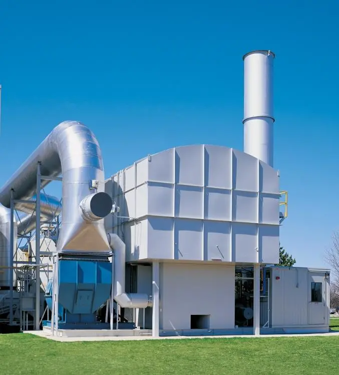
Conventional three-chamber systems repeatedly open and close multiple valves. Zenviro Tech’s patented rotary distributor instead directs flow continuously through inlet, purge and outlet sectors beneath one combustion chamber.
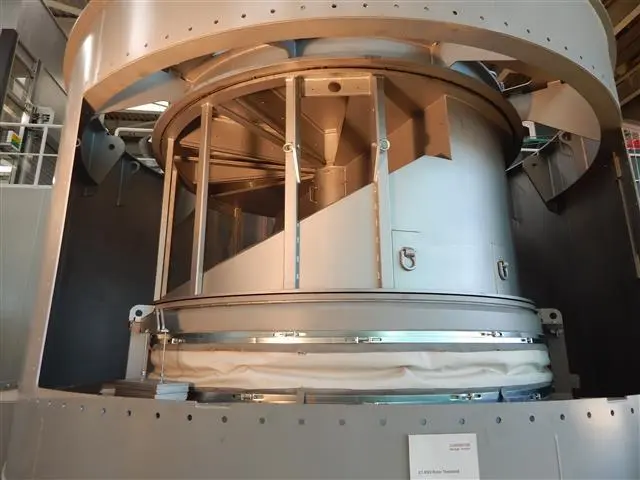
The distributor’s inlet, purge and outlet wedges progress around the segmented ceramic beds. Each bed repeatedly stores heat, preheats incoming exhaust and receives clean-gas purge without a bank of fast-cycling poppet valves.
The rotating distributor aligns each ceramic section with one of three duties. Continuous purge follows the inlet sector, limiting untreated-gas carryover before that section becomes an outlet path.

A variable-speed process fan collects the exhaust and sends it into the RTO vessel.
The inlet wedge routes exhaust upward through hot ceramic media, bringing it close to oxidation temperature.
Oxidation occurs in the common combustion chamber; the burner adds only the heat required by the operating duty.
Clean hot gas flows down through another sector, reheating the media before leaving through the outlet.
A following purge wedge flushes residual process gas from the media before it rotates into outlet service.
Treated air exits through the common outlet and is discharged through the stack.
The benefit is not merely fewer components. Continuous distribution reduces switching events, keeps pressure and temperature more stable, limits pollutant puffs and removes several utility and maintenance demands associated with valve actuation.
A single distributor and drive replace multiple valves, actuators and associated switching hardware.
Continuous rotation avoids the sharp pressure pulse produced when conventional RTO valves change position.
Only the bed sector transitioning from inlet to outlet is purged, reducing purge volume and recovered-heat loss.
All heat-exchange sectors sit beneath one combustion chamber, reducing footprint per unit of treated airflow.
Graphite sealing and protected seal placement reduce exposure to the dirty process stream and particle buildup.
Slow rotary motion eliminates the repeated mechanical impact and air-release noise of fast valve cycling.
Zenviro Tech’s published comparison highlights how the rotary layout changes the maintenance burden and flow behavior rather than simply rearranging conventional chambers.
| Design Point | Conventional 3-Chamber RTO | Zenviro Valveless Rotary RTO |
|---|---|---|
| Flow control | 9 valves and 9 drives | 1 rotating distributor and 1 drive |
| Operating action | Repeated rapid switching | Continuous rotation |
| Published pressure fluctuation | Approximately ±2 mbar | Approximately ±0.15 mbar |
| Actuation utility | Compressed air normally required | No compressed air for valve actuation |
| Purge section | About 1/3 of media volume | About 1/10 of media volume |
| Arrangement | Three reactor chambers | Single reactor / smaller footprint |
Comparison values reproduce the design comparison presented in Zenviro Tech’s supplied product material; final performance depends on the engineered application.
The rotating assembly is built around sector partitions and graphite sealing surfaces. Locating seals away from direct process-gas exposure supports longer seal life, while the geometry helps tolerate dust and deposits.
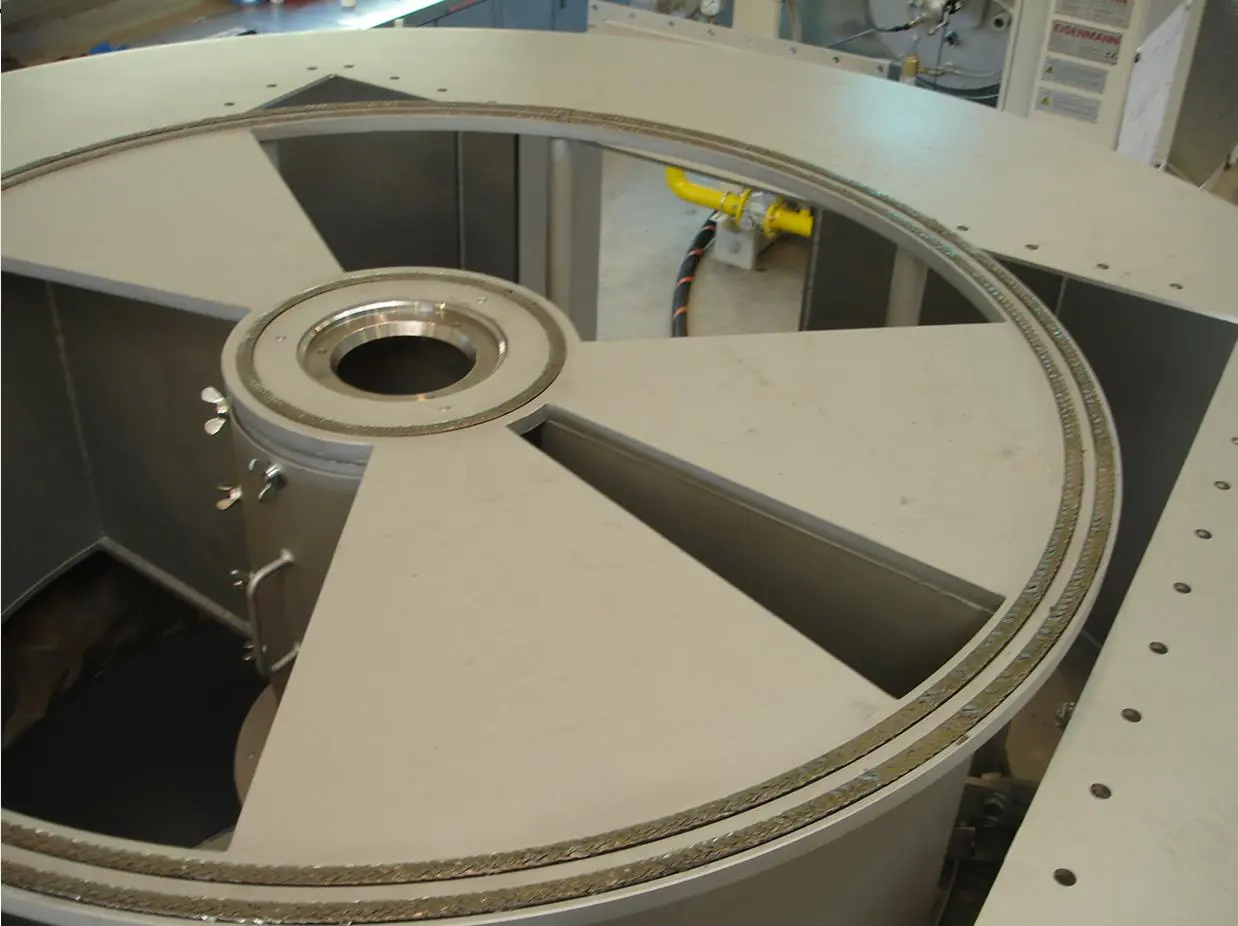
Continuous circumferential sealing separates inlet, purge and outlet duties while resisting process deposits.
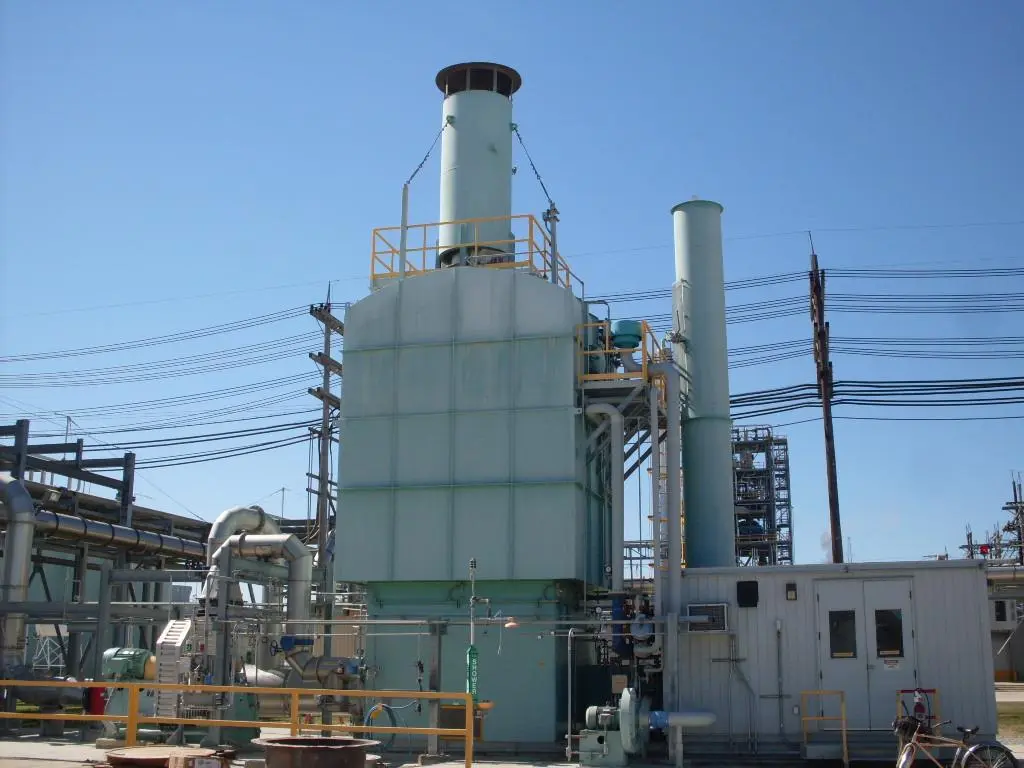
Single-vessel construction integrates the heat-storage beds, combustion chamber, fan, ducting and controls in a compact arrangement.
The design is suited to large exhaust-air volumes at high or low pollutant concentration. Stable pressure behavior is especially valuable where an RTO is connected to sensitive production tools and continuous manufacturing lines.
Review Your Application →Share airflow, VOC composition, temperature, particulate loading, LEL range and required emissions performance.