

Home  ›  Capabilities  ›  Design & Engineering
Instrument Skid Engineering

DESIGN &
ENGINEERING

Process intent becomes a specified, coordinated, fabricated and fully verified instrument skid through one controlled engineering workflow.

Explore the workflow ↓
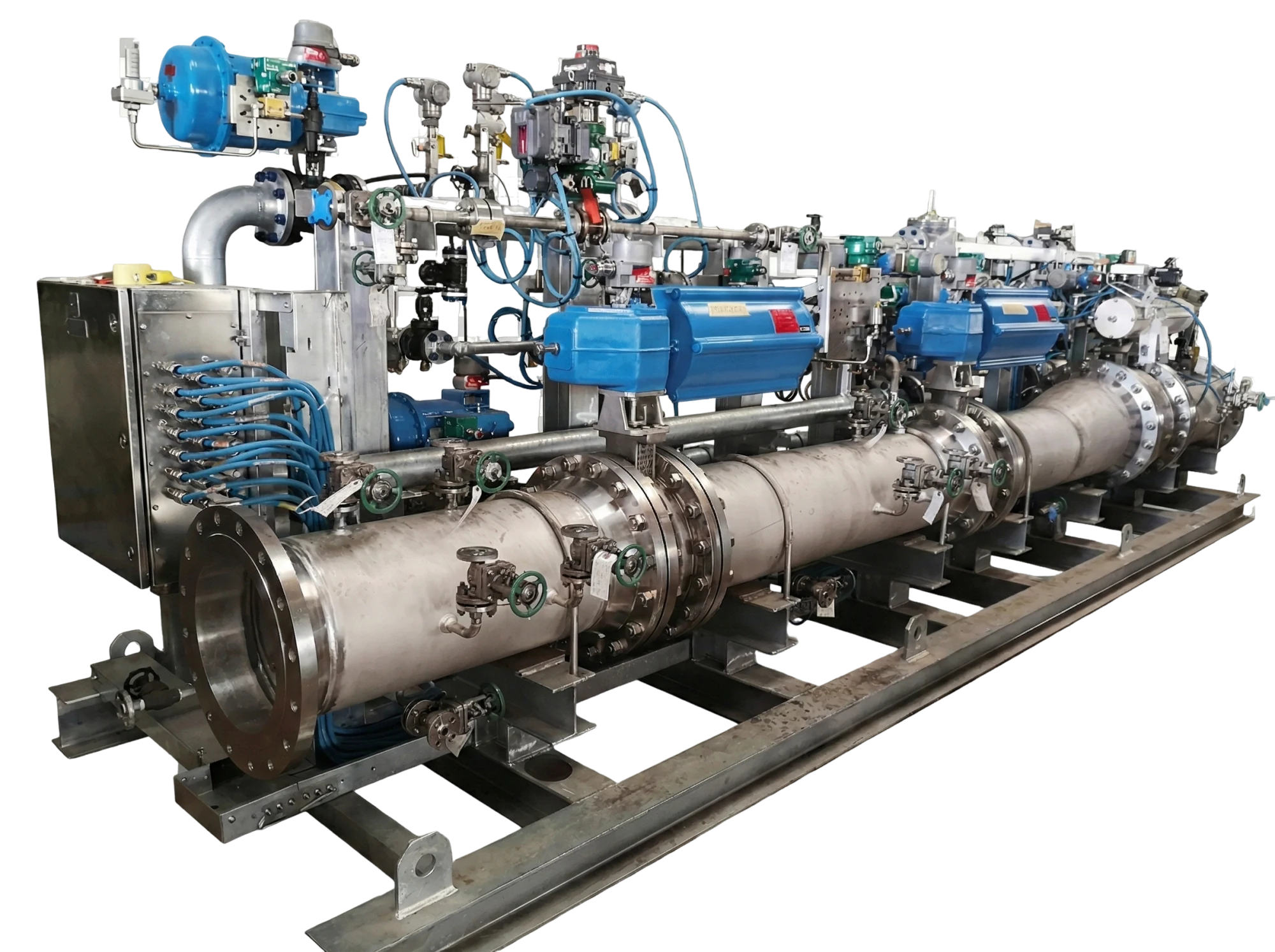
Integrated instrument skid with piping, valves and instruments
Interactive 3D modelDrag horizontally to rotate · Click a region to separate nearby assemblies
Loading 3D model · 0%
Engineering Workflow

Six steps.
One controlled process.

A P&ID defines what the system must do. Engineering defines exactly how every instrument, valve, connection and interface will be built.
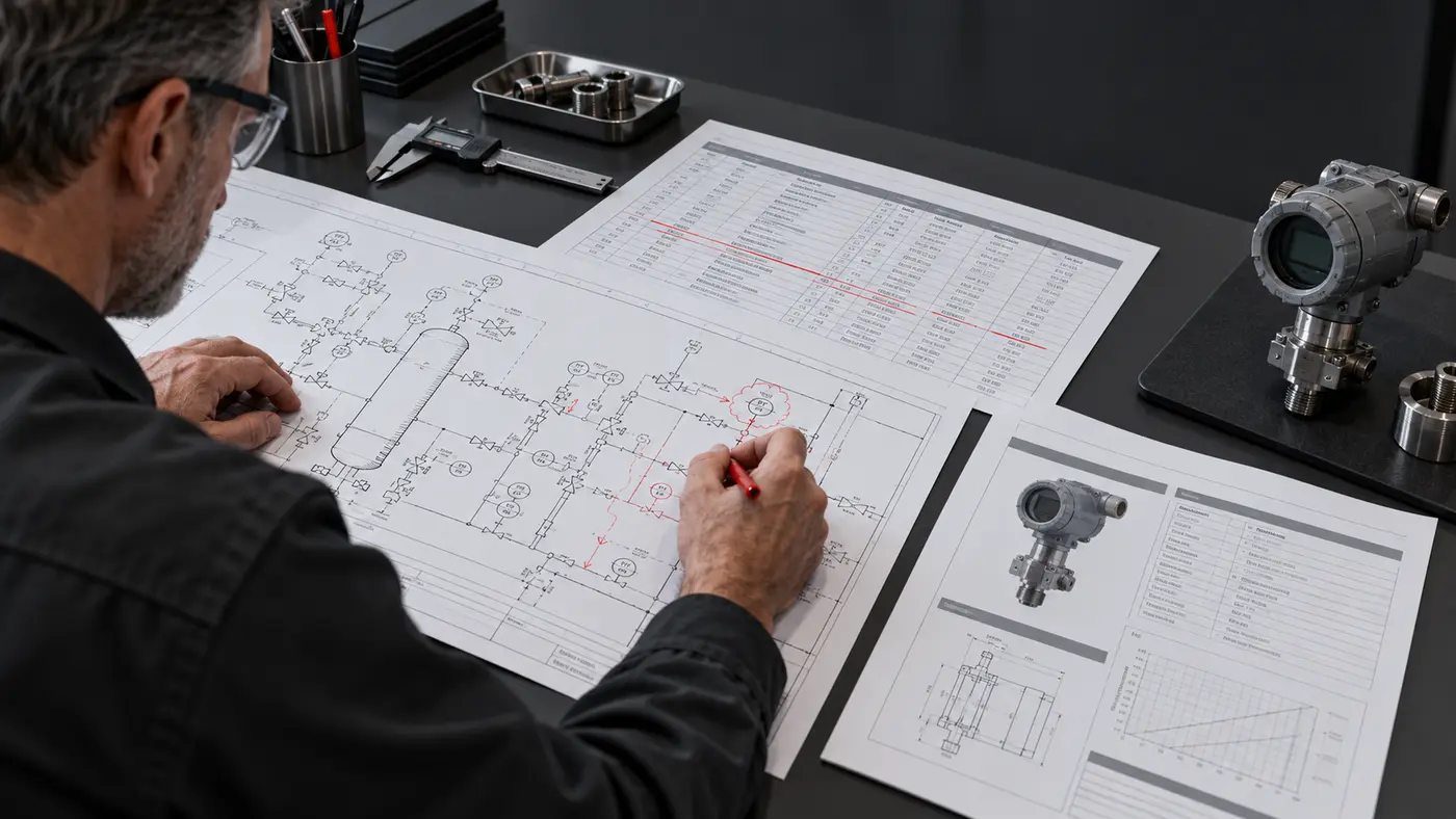
Instrumentation engineer reviewing a marked-up P&ID and transmitter datasheet
Steps 01–02Define the system.
Specify every component.
01 / DEFINE

Review & Define

Set the technical baseline before detailed design.

  • P&ID review
  • Package boundaries
  • Codes & design basis
Outputs
P&ID Mark-UpDesign Basis
02 / SPECIFY

Extract & Specify

Turn each tag into controlled engineering data.

  • Instrument & valve lists
  • Ranges, materials & signals
  • Technical datasheets
Outputs
Instrument IndexDatasheets
Engineer checking valves and instruments against a 3D instrument skid model
Steps 03–04Select the hardware.
Integrate it in 3D.
03 / SOURCE

Select & Procure

Match compliant equipment to the approved specification.

  • Technical RFQs
  • Bid evaluation
  • Vendor document review
Outputs
TBEApproved Purchase
04 / INTEGRATE

Integrate in 3D

Create an accessible and maintainable skid layout.

  • Piping & tubing routing
  • Access & maintenance
  • Clash and transport review
Outputs
3D ModelGA & Isometrics
Technician performing calibration and factory acceptance checks on an instrument skid
Steps 05–06Build the skid.
Verify before delivery.
05 / BUILD

Fabricate & Assemble

Integrate the complete package under controlled procedures.

  • Frame & pipe fabrication
  • Valves, instruments & tubing
  • Panels, wiring & tagging
Outputs
Integrated SkidInspection Records
06 / VERIFY

Verify & Deliver

Prove performance before the skid leaves the workshop.

  • Calibration & leak tests
  • Loop and I/O checks
  • Functional FAT
Outputs
FAT-Tested SkidAs-Built MDR
One Tag, Fully Defined

A symbol is only the beginning.

P&ID Input
PT-101

Skid inlet pressure

PT-101 / Instrument Record

ServiceSkid Inlet Pressure
MediumNatural Gas
Range0–10 barg
Connection½ in. NPT
Wetted Material316L SS
Signal4–20 mA + HART

Coordinated with: root valve, manifold, tubing, fittings, bracket, cable gland and I/O.

Controlled Output

Ready to build.
Ready to verify.

The result is an integrated skid supported by controlled engineering records and final test documentation.

Approved P&IDInstrument IndexValve & I/O ListsDatasheetsGA & IsometricsHook-Up DrawingsFAT RecordsAs-Built MDR
Instrument Skid Modules

From process definition to a skid ready for site tie-in.

Return to Instrument Skid Modules

Discuss Your Project →