Home › Instrument Skid Modules › Boiler Fuel Gas Pipe Rack
Burner Management Skids / Boiler System

BOILER FUEL GAS
PIPE RACK

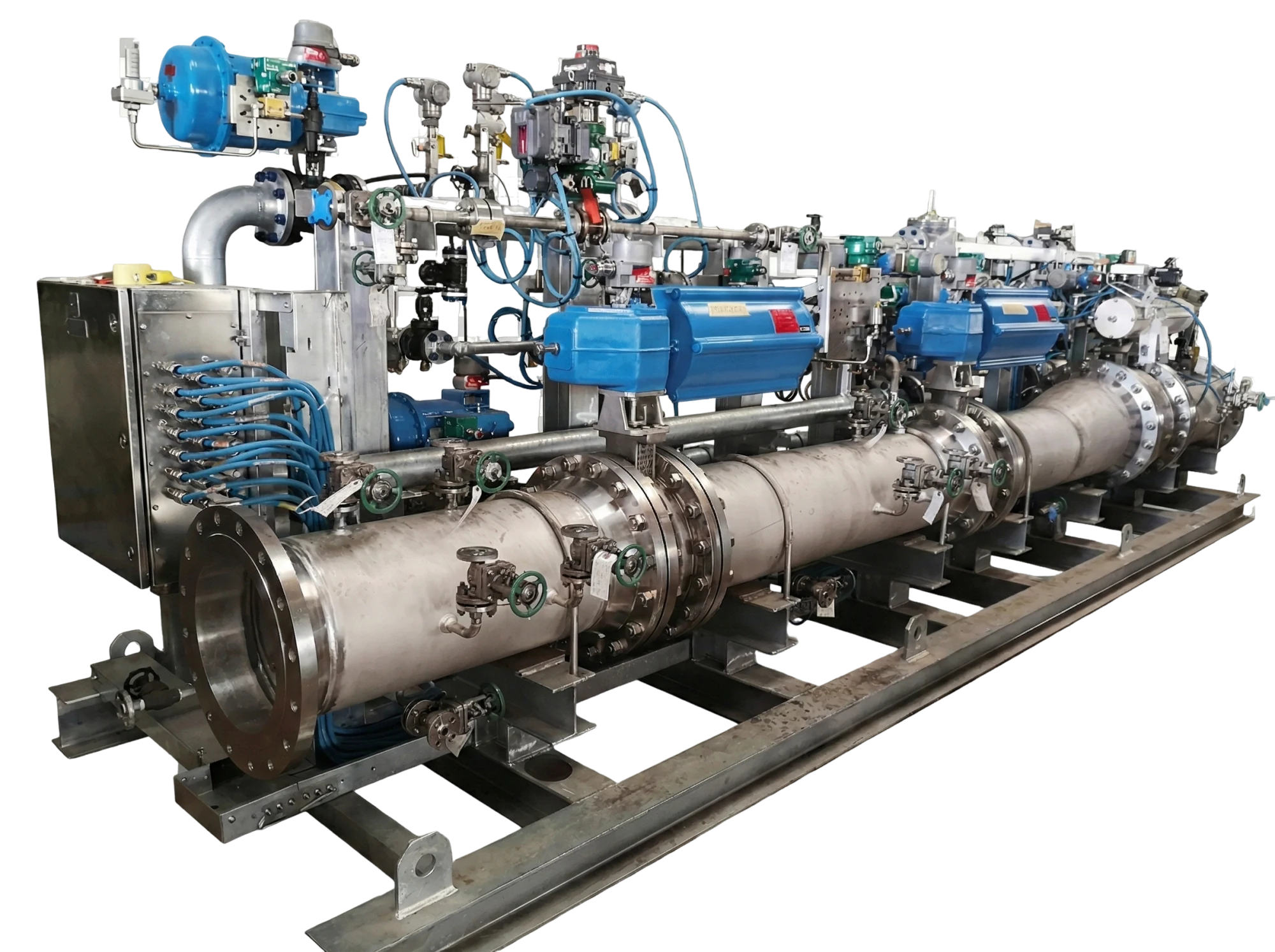
An integrated boiler fuel-train skid bringing fuel conditioning, metering, controlled isolation, ignition supply and utility distribution together on a common structural frame.

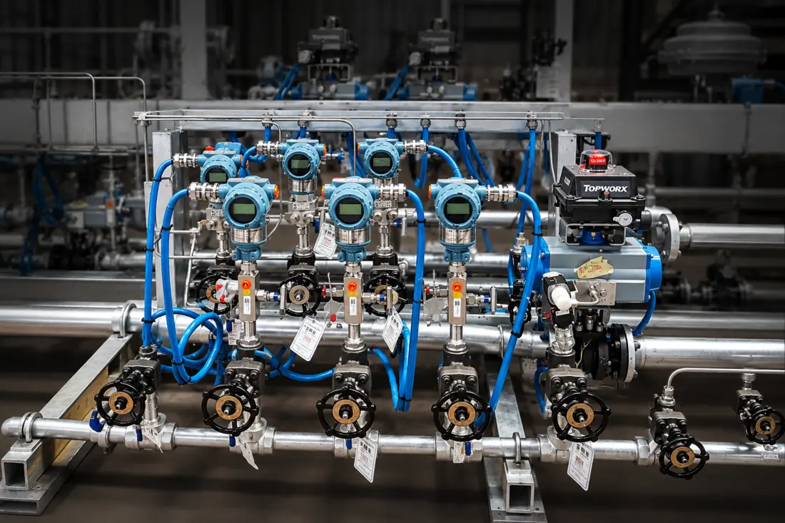
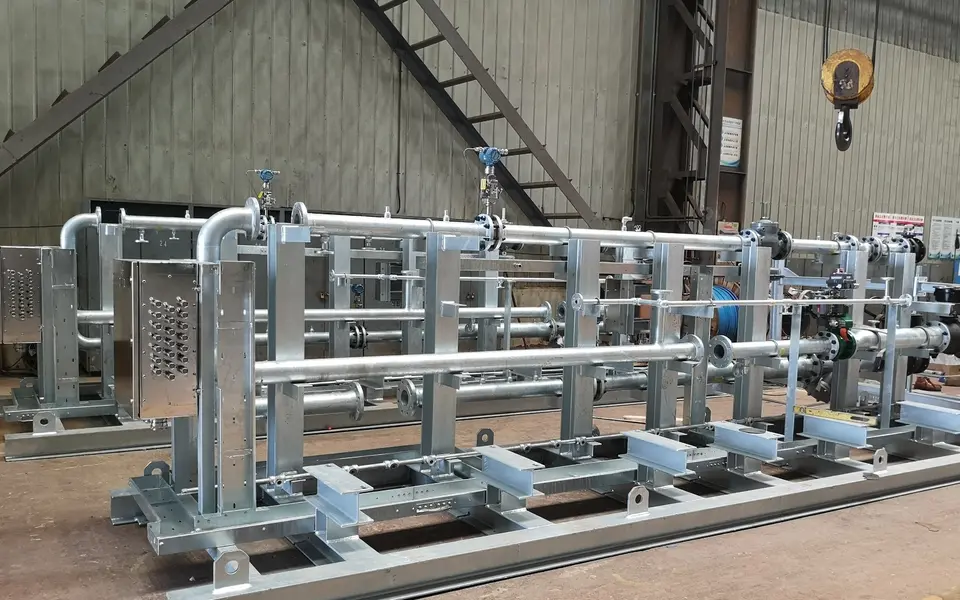
Representative assembled burner-management fuel skid with piping, valves and instruments
Representative fuel-train skid integration; project configuration follows approved engineering drawings.
Media & Flow Arrangement

Three fuel trains.
Two supporting utilities.

The boiler arrangement contains five principal functional circuits: process off gas, natural gas / waste natural gas, igniter gas, nitrogen purge and instrument air. Natural gas and waste natural gas enter through separate inlet legs before joining a common main-burner train. Igniter gas is a branch of the natural-gas supply.

Process off gas
Fuel conditioning, metering & isolation
Main burners
Natural gas + waste natural gasTwo separate inlet legs
Separate inlet conditioning / metering → common fuel train
Main burners
Igniter gasNatural-gas branch
Dedicated ignition-fuel train
Burner igniters
Nitrogen
Purge circuit
Process-off-gas train
Instrument air
Air distribution & regulation
Valve actuators & flame scanners

Functional overview only—not a fabrication drawing or an operating sequence. Vents, drains, sensing lines and downstream branches are not counted as separate main trains.

CircuitMedium carriedPurpose & arrangement
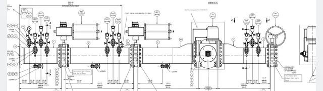
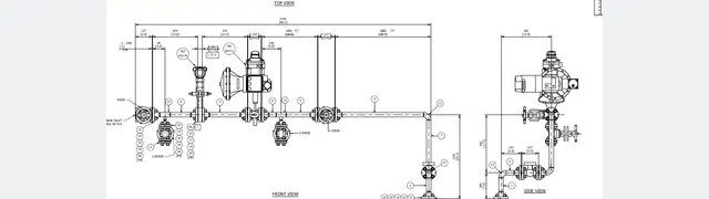
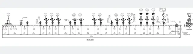
Process off gas train drawing thumbnail01 · Process off gasCombustible process off gasDelivers process-derived fuel to the boiler burners. Gas composition and operating conditions are defined by the project process basis.
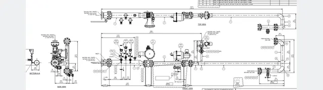
Natural gas and waste natural gas train drawing thumbnail02 · Main NG / WNG trainNatural gas and waste natural gasTwo separately conditioned / metered incoming fuel lines converge into a common main-burner supply train.
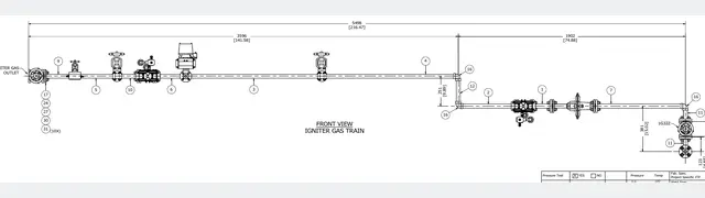
Igniter gas train drawing thumbnail03 · Igniter gasNatural gasA dedicated small-bore ignition-fuel train supplied from a natural-gas branch, feeding the burner igniters.
Nitrogen purge train drawing thumbnail04 · Nitrogen purgeNitrogenProvides the purge connection into the process-off-gas piping; it is an auxiliary utility, not a fuel stream.
Instrument air distribution drawing thumbnail05 · Instrument airInstrument airDistributes regulated air to pneumatic valve actuators and the flame-scanner air connections shown in the P&ID.

Counting basis: three main fuel trains plus two auxiliary utility circuits. This describes system functions, not the number of individual pipe pieces or all physical inlet and outlet connections.

Design & Supply Scope

From approved process design to a fabricated, integrated skid.

The supply boundary combines piping, structural steel, valves and instrumentation, electrical interfaces and factory verification. The following groups summarize the documented scope rather than reproduce a component-by-component bill of materials.

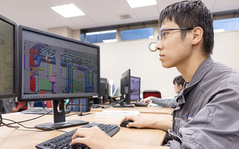
Engineer reviewing a three-dimensional piping model at a CAD workstationCoordinated instrument manifold and valve layout

Engineering & Interface Development

Translate approved P&IDs, equipment data and general arrangements into fabrication details and shop drawings. Coordinate pipe supports, access, structural interfaces, instrument tubing, cable routing and plant tie-ins, supported by an agreed inspection and test plan.

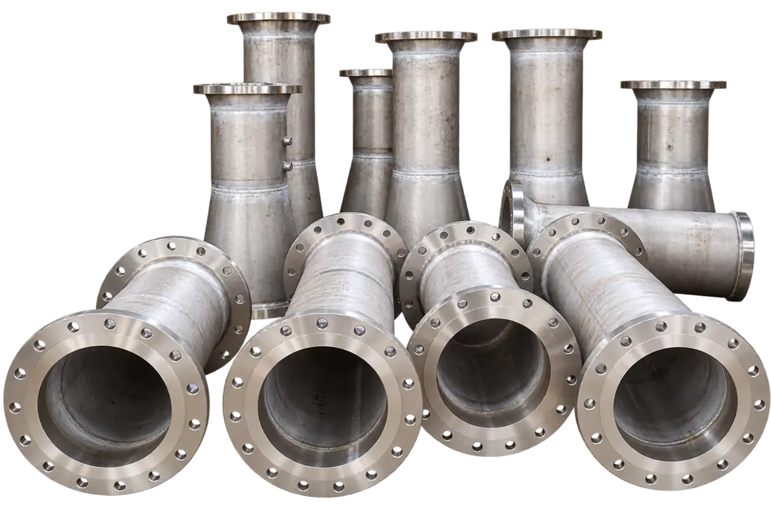
Boiler fuel-gas pipe rack during structural and piping assemblyFabricated stainless-steel flanged pipe spools

Piping & Structural Fabrication

Provide and assemble process piping, fittings and connections on a steel base frame with pipe supports, lifting provisions and grounding points. Material selection, welding and protective coating follow the approved line classes and project specifications.

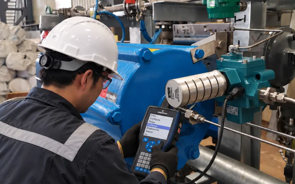
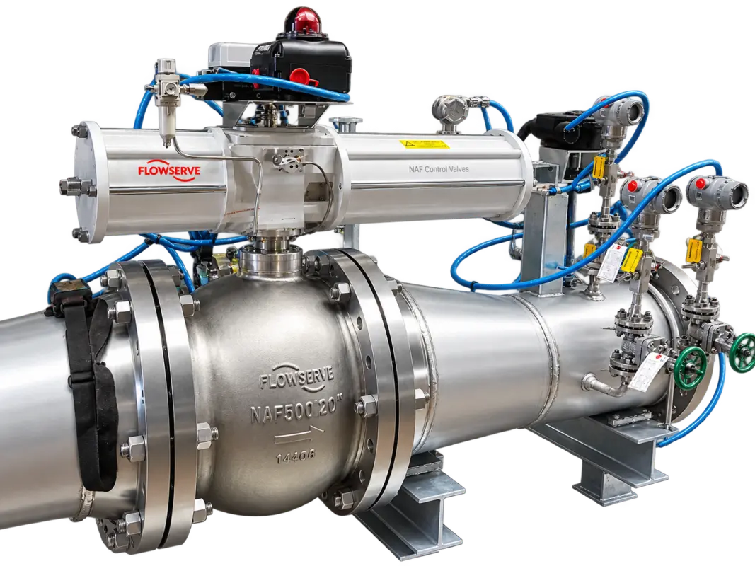
Engineer using a handheld communicator to commission a valve positionerIntegrated control valve actuator and field instruments

Valves, Instruments & Electrical Integration

Integrate fuel conditioning, flow measurement, pressure regulation, control and shutdown functions with instrument-air distribution. Route factory wiring to separate DCS and BMS / SIS junction-box interfaces. Valve and instrument procurement, or installation of customer-supplied items, follows the awarded scope.

Inspector checking equipment and recording inspection results

Inspection, Documentation & Delivery

Complete approved material and weld verification, dimensional inspection, pressure testing and assembly checks. Deliver the manufacturing quality dossier, identification, preservation and shipping preparation, with technical site support as agreed.


Design & Manufacturing References

Project-defined codes.
Traceable execution.

The requisition and drawings reference international and Chinese requirements for piping, structural fabrication, welding, hazardous-area equipment and enclosure protection. Mandatory local requirements and the contract design basis govern applicability.

DisciplineRecorded referencesApplication
Process pipingANSI / ASME B31.3; GB/T 20801Process-piping design and fabrication, with Chinese pressure-piping requirements and applicable permits / stamps. Individual piping details also reference GB/T 20801 inspection provisions.
Structural steel & weldingAISC; AWS; JB/T 1613Structural fabrication and applicable project welding requirements. Specific acceptance criteria follow approved drawings and procedures.
Welding qualificationASME Section IXWelding procedures and personnel qualification as referenced in the inspection and test requirements.
Hazardous-area equipmentGB 3836; Zone 2, Group IIC, T4Electrical and instrument suitability for the area classification recorded in the general-arrangement notes.
Enclosure protectionNEMA 4X; IP66Enclosure protection requirements stated in the project drawings.
Fire & combustion safetyUFC; UL; NFPAFire-protection and combustion-safety requirements applied where specified by the project and governing authority.
Coating & quality managementJB/T 1615 / SSPC; EN ISO 9001 or equivalentProject coating / preservation specifications and the quality-system requirement in the requisition; not a claim of product or supplier certification.
Factory Verification

Quality built into each fabrication stage.

Before Fabrication

Review shop drawings, material requirements, welding qualifications, weld / NDE maps and the inspection and test plan before production begins.

During Assembly

Maintain material traceability and inspection records, verify dimensions and welding, and check installation against the approved piping and instrument arrangement.

Before Shipment

Hydrotest pipe spools and pneumatically test assembled trains as required by the approved ITP. Complete records, identification, preservation and packing for delivery.

Define the Project Basis

Coordinate the fuel rack with your boiler system.

Share fuel composition, flow and pressure ranges, burner arrangement, utility conditions, area classification and the required plant control interfaces.

Discuss Your Fuel Skid →